standard cells, IO cells and memories. SolutionWare does characterization
and modeling. CellOpt generates new cells with minimized power
dissipation. YieldOpt generates best/worst case netlists under
process variation. ChipTimer generates a design specific
library through CellOpt. UnBlock and RcBack split a custom
and possibly flat design into library cells and interconnect.
Each of these tools interface to SolutionWare at some level.
Here is an overview of the library generation process, using
SolutionWare:
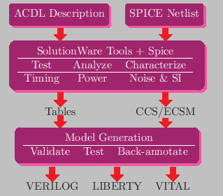
The SolutionWare tool set automates various tasks involved in
setting up a design libraries: functional verification, timing and
power characterization, model generation, validation
and documentation. Complexity of the cells could range from standard
cells to various types of IO's and memories, which all are described
using a simple description language, ACDL. Electrical information is provided through a SPICE netlist, which describes the connectivity of various
electrical components and parasitics making up the cell. These two inputs are specific to each cell. The tools determine all the
relevant electrical parameters, generate stimuli for measuring them,
carry out the actual measurement using Spice and and report the results
in various formats like NLDM, CCS and ECSM. It interfaces to several
different spice simulators, like Hspice, Spectre, Smartspice, Eldo, Hsim etc.. For memories, use of a fast simulator like Hsim or Ultrasim
is necessary.
ACDL
ACDL
 description is the entry point for
most of the tool set. For most cells, it consists of a single statement
expressing the relationship between the inputs and outputs, which is intuitive to most engineers. In spite of
its simplicity, ACDL is quite powerful in expressing the relationships
between the cell inputs and outputs and cell functionality. Cells such
as complex flip-flops, scan cells, adders, etc. are easily described in
ACDL. It is assumed that it is a “golden” representation of the cell
functionality. All views, including the circuit level implementation
are checked against the functional specification in the ACDL description.
ACDL is very simple, the following describes a flip-flop with reset:
description is the entry point for
most of the tool set. For most cells, it consists of a single statement
expressing the relationship between the inputs and outputs, which is intuitive to most engineers. In spite of
its simplicity, ACDL is quite powerful in expressing the relationships
between the cell inputs and outputs and cell functionality. Cells such
as complex flip-flops, scan cells, adders, etc. are easily described in
ACDL. It is assumed that it is a “golden” representation of the cell
functionality. All views, including the circuit level implementation
are checked against the functional specification in the ACDL description.
ACDL is very simple, the following describes a flip-flop with reset:
*header D Flip-Flop with Clear
Q = !RB ? 0 : rising(C) ? D : "p"
which is a concise specification of flip-flop behavior. More complex
cells can be described in similar manner, one equation for each
output. Memory cells have their own special format, similar to ACDL, but read/write and address modes need to be described. Synchronous
rams with all sorts of controls, single or multiple ports, of
various sizes and depths can be modeled easily.
LTI is unique in the way we model cells, by requiring the user to enter
the function. Almost all of our competitors try to analyze the circuit
connectivity and figure out what the function is. This approach may work well for simple combinational cells, but difficult to extend to complex cells
like flops with clock enables, special cells like semi-synchronous
cells etc.. We have seen cases where such recognition software failed
even for a NAND gate. If the logic is not recognized correctly, there may not be a way of correcting it. On the other hand, with ACDL approach, we can
even model memories, and compare functions for every generated model.
MakeLib
Unlike most EDA tools, LTI's tools do not have graphical
interfaces. This is mainly due to very little need for
interactive use during modeling and creation.
Almost all the inputs which can be provided by an intelligent
user are automatically generated, thus eliminating the need for
a graphical interface. Instead, we provide a flow manager,
makelib which requires a policy file, .libcharrc,
which contains a description of the user preferences and of
the environment under which the tools will be working. In
addition, a list of cells which need to be processed or modeled
and their associated spice data is also required as input.
As the contents of library change, only the data associated
with new cells are generated. If primary inputs for the
cell change, like its spice netlist, all of its associated
data are regenerated.
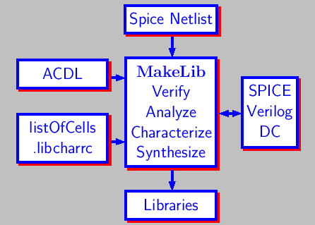
For cell characterization and library generation, there is
only one command the user needs to know, MakeLib. It reads in a list
of cells making up the cell library,
and sequences all the steps necessary for the characterization
and library building.
MakeLib automates almost all of the tasks necessary for
creating a standard cell design library. Specifically
these are the steps one needs to take in order to do
cell characterization and generate libraries.
Issue a library building command,
makelib veriloglibrary
makelib libertylibrary
makelib vitallibrary
and MakeLib will step through all the stages of
verification, analysis, characterization, modeling and model verification as may be necessary, and it will generate a tested and verified library, compiled
and ready to use.
Built-in Parallellism
If the same command is issued again, MakeLib starts a concurrent job for the same goal. There are no special steps necessary for utilizing multiple
machines and cpus other than making sure that there are enough licenses
available and file systems are consistent across machines. Using the
same list of cells and the same configuration file, as many copies of
MakeLib can be run concurrently as the number of available licenses.
MakeLib distributes the jobs among all available machines.
Easy to Configure
The setup file .libcharrc is interpreted by
perl.
This allows
the customization of any parameter or option in setup file
at run time for different cells, different PVT corners
and for different stages of library creation and modeling.
The default setup file is self documenting, and lists all
available options. In this file, type of simulator to use,
how to interface to SPICE models, how to execute SPICE,
thresholds, supplies, characterization corners, min and
max load range for each cell, maximum rise and fall times,
and table information for characterization are specified.
Automatic Verification and Test
LTI tools have extensive verification and test capabilities.
Basic functionality tests are performed by circuit level simulation.
Verilog and Vital models are verified through the use of automatic
test benches. Synthesis models are verified formally. SDF back-annotation can be checked between simulation models and synthesis library. Finally, the
accuracy of delay calculation can be checked for each cell and timing
arc under different load conditions with a single command:
makelib ccstests
which can be used to verify CCS and ECSM models.
Copyright (c) 2019 Library Technologies, Inc., All Rights Reserved.