CellOpt: Power and Delay Optimization
"Finally, we got the flip-flop that you optimized, working on the silicon. Our chip became functional. We gained about 30% on cell area, and that turned out about 4-5% gain on total silicon area utilization. Perhaps we have been too cautious and didn't use them in high frequency blocks."
- Taji Isik, ICS
Power management is the most significant design challenge facing IC
designers today. There are widely used system level techniques like
low power modes, clock gating techniques and custom low power circuits
to address the problem. However, the situation is desperate enough
to take extreme measures like special processes and very low voltages,
power versus performance trade-offs, etc.
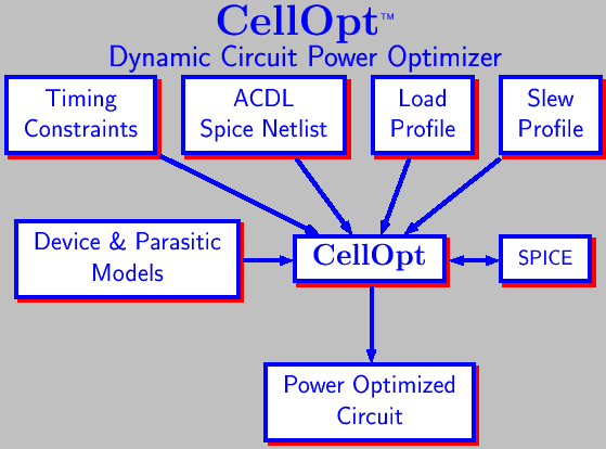
CellOpt is a dynamic circuit level power/timing optimizer designed to minimize
the power dissipation of standard build blocks like logic gates and
sequential elements, with optional timing constraints, by
properly sizing the devices used in the circuit.
After all, energy is consumed by these components,
and how well they are designed and how well they fit to their particular
use on the chip is of paramount importance.
Traditionally, cell designers follow certain ratio rules to
accommodate drive requirements, but the primary design goals are
usually the efficiency of the layout and ease of portability. Power
characteristics of the circuits usually fall to the wayside as their
proper characterization is beyond the capabilities and time limits of
most circuit design engineers.
Short Circuit versus Capacitive Power
There are two competing events at the circuit level. One is the
charge storage capacity of the circuit which grows with bigger
devices and increases as the circuit switches faster. The other
is the short circuit power dissipation: if the
transition is fast, this component will be small; if it is slow, it
could be significant. The optimization problem balances these two
competing events against each other.
SPICE is the most reliable tool.
At the circuit level almost all the capacitors are non-linear. Short
circuit current depends very strongly on the device characteristics.
The measurement of their precise magnitude and duration is beyond the
capabilities of non-spice based tools. Usually the amount of energy
is very small, in the range of fractions of pico-Joules. Small errors may throw
the solution off the target.
There are critical path based device sizing tools which are much faster
in giving you an answer although it is usually wrong. Their usefulness
drops off very fast as you move away from inverter chains. CellOpt is not a critical path optimizer. It looks at all the paths simultaneously:
critical, non-critical, switching and non-switching.
The effect of each path is weighted statistically, mimicking its
actual realization under
typical usage models. Critical path based optimizers look at only a
small part of the circuit at a time. As they adjust some paths, they
can not control their adverse effects on other parts of the circuit.
Inputs to CellOpt
CellOpt needs to have a spice netlist which is functional.
It also requires a functional specification for the cell in
ACDL format. The cell should be cleared by SpiceTest before
optimization is performed.
It also needs capacitive loads for each output, and input rise/fall times for each input.
One can specify various timing constraints in the form of
upper limits on input/output delays
and output rise/fall slew times, and for sequential cells setup times for different input pairs. Individual
paths can have different constraints.
The tool has a
Perl based setup file to define various choices. Using Perl,
one can override various setup parameters and constraints for an individual
cell. A problem with pre-layout netlist is the estimation
of device parasitics.
Proper modeling of the device parameters is important for the reliability
of the optimization results. The user is expected to provide a Perl function which
returns the device parameters given its length and width. It is also
also possible to generate these functions automatically if the circuit
layout topology is not going to change and if you can generate the layout
automatically.
Input switching rates are calculated by CellOpt. The user can
increase the toggle weight associated with each inputs.
CellOpt is normally executed by MakeLib. MakeLib verifies the functionality of the circuit using SpiceTest, analyzes its power
dissipation modes using StateGen and starts the optimization process.
It generates a new netlist with modified device sizes.
Timing versus Power
Timing requirements take precedence over power optimization.
Any constraints on the circuit will restrict any possible
optimization which can be done. If it can't change the size of the
output devices, which are the most critical for power dissipation,
emphasis will be placed on the other devices, like smaller devices
at the inputs. Depending on the initial circuit size, it is possible
to end up with a lower power, faster and smaller circuit.
Conflicts between the constraints are resolved using their
user assigned weights.
Low Power Strategy
Typically, clocks are the most heavily loaded nets, and consume the
most of the energy. Clock network optimization by LowSkew can help reduce the clock power usage without introducing
skews. Registers driven directly by clocks could be optimized
for low power by CellOpt. These cells are the most likely
to toggle and consume energy. Any improvement in their
power usage affects the energy consumption.
Finally for core logic, building
a “fixed-delay” library with CellOpt can reduce the
power dissipation without affecting the performance. Usually,
standard cells are designed for fixed rise/fall times. However,
what counts in a gate level design is the total delay through
the cell. By distributing the delay throughout the gate,
one can design more energy efficient cells while meeting the
performance goals.
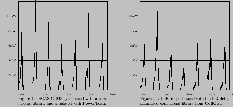
Faster circuits use more energy. Although
this is true, it does not exclude good design practices. Figure 1
shows power waveforms for C1908 from ISCAS benchmark circuits
after synthesizing it for zero delay using a commercial library.
CellOpt was used on this library to generate the fastest possible
worst case pin-to-pin delays. Figure 2 shows the power waveforms
generated by PowerTeam after synthesizing the same circuit with
the optimized library for best timing. This speeds up slow timing paths,
and slows down fast timing arcs, with small change in the average
signal delay through the cell.
The new implementation
is slightly faster, 1.725ns versus 1.706ns, and more energy
efficient according to the synthesizer, by about 13%. It is
noteworthy that peak power varies by as much as 50% between
the two implementations, depending on the inputs. Over a much
longer interval, energy use difference is 10% based on PowerTeam simulations. For more significant reductions such as 30%, one needs to use
the faster cells on the critical paths, and the slower, more energy efficient
cells on the non-critical paths. Such paths are the most common.
Copyright (c) 2019 Library Technologies, Inc., All Rights Reserved.