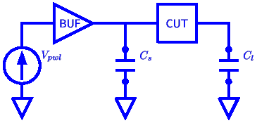
The cell is embedded in a test circuit where it is driven by “real” live drivers and loaded with the maximum loads at its outputs. Automatically created SPICE stimuli are applied and the outputs of the circuit are compared against the expected values. Especially for new cell libraries, SpiceTest has been very effective in identifying faulty cells.
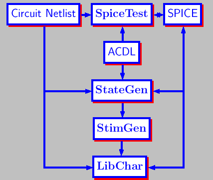
ACDL description of the cell is the specification upon which inputs and expected values of the outputs are based. Even for complex cells, test vectors can be generated in seconds. The Cell-Under-Test is driven by buffers after loading its inputs and outputs. This setup tries to be as close to In-Circuit-Testing as possible. SpiceTest generates a SPICE netlist which includes the model cards, environmental parameters, test vectors generated from ACDL, an instance of the Cell-Under-Test, its drivers and loads. Finally, SPICE is called to do circuit level simulation. Its output is compared to the expected values at strobe points determined by SpiceTest. Any unstable outputs and functional errors are reported to the user. A SpiceTest user does not really need to know how to use SPICE and do circuit simulation. The cell design and verification process can be accelerated by delegating the verification part to SpiceTest.
Before characterization starts, various test vectors are analyzed for state-dependency. State-dependent delay, power, input capacitance as well as setup/hold conditions are identified by StateGen.
Automatic Stimuli Generation One of the unique features of Solutionware is its integrated test vector and stimuli generator. User does not need to specify any stimuli to be passed to circuit simulator. It is all automated. The functionality of the basic cells is quite simple, and there are few inputs. However, when the cell is implemented at the circuit level, it is quite possible that it may not be implemented correctly. This is especially true for complex flip-flops, though we have seen quite a number of combinational cells not matching their expected behavior. By separating the description and circuit level implementation, an extra layer of reliability checking could be added to the cell design process. The most time consuming and error prone activity in the library creation process is the stimulus generation. StimGen eliminates this bottle neck by synthesizing the stimuli from a higher level description of the cell, ACDL, which is also the entry point for most of the LTI tools. StimGen generates inputs for LibChar, the characterizer. These are generic spice inputs, which are independent of the circuit simulator, of the supply voltages and various timing parameters. For almost all ASIC library cells, including I/O and scan cells, the stimuli can be generated automatically. Stimuli for measuring the following parameters can be generated automatically for any cell which can be described in ACDL, which partially include
|
|
|
|
|
|
|
|
|
|
|
|
|
|
|
|
|
|
|
|
|
From analysis of an ACDL description of the cell, StimGen determines what the appropriate parameters are and writes out stimuli accordingly. Any cell with at most one internal state, irrespective of the number of inputs, and its functional complexity can be handled automatically. For multiple internal states, multiple equations are required in the ACDL description.
extracted from layout, and a stimulus file describing each parameter to
be calculated. Stimuli are generated by
StimGen automatically from the ACDL
![]() description of the cell and the state-dependency information from StateGen. The actual values of the supply voltages,
temperatures, SPICE models to use, delay models, threshold voltages are
specified in LibChar configuration files, .libcharrc. All these variables can be
grouped into various corners.
description of the cell and the state-dependency information from StateGen. The actual values of the supply voltages,
temperatures, SPICE models to use, delay models, threshold voltages are
specified in LibChar configuration files, .libcharrc. All these variables can be
grouped into various corners.
There are several ways of measuring pin-to-pin delays and transition times at the user's disposable. Same setup is used for measuring power, supply currents and input loads. LibChar can optionally produce CCS, ECSM, CCS-power and signal integrity data. Execution time is highly optimized. Various algorithmic techniques are employed to reduce the number and duration of SPICE runs. LibChar and its friends provide the most robust and reliable characterization and modeling environment. Same set of tools are used across cell, IO and memories, providing a consistent set of features and capabilities across all of them. ACDL is especially suitable for handling non-conventional cells, and good for any type of logic family including dynamic and current mode logic families.
There are also quite a bit of variation on how each parameter is measured. It is difficult to disagree on how input-to-output delays are measured, but there is considerable room for setup/hold measurements, input capacitance, static and dynamic power. On such quantities, the algorithms and techniques make a big difference. More often than not, the alternative techniques are wrong or irrelevant to the intended use.
Another false technique used is interpolation. Instead of running the whole sequence of input slope and load points, a few are run and the rest are obtained from interpolation. This is especially true in the face of process variation which requires hundreds or thousands of different libraries. Cutting short of proper characterization steps adds to the process variation and increase it rather than help manage the problem. To address process variation, our YieldOpt product is available without cutting corners.